Table of contents

When designing heavy machinery like cranes, excavators, or solar trackers, choosing the right rotational component is a critical task. If you underestimate the forces, the bearing will fail catastrophically. Conversely, if you oversize it, you will waste valuable space and budget.
Therefore, mastering the slewing ring bearing calculation process is the ultimate way to ensure job site safety and cost efficiency. Sizing a turntable bearing requires a precise analysis of complex multi-directional forces.
In this comprehensive engineering guide, we will break down the essential formulas, load profiles, and steps required to complete an accurate slewing ring selection calculation.
Step 1: Identify the Three Core Loads
Unlike standard small-diameter ball bearings, a slewing ring usually acts as a structural joint. Consequently, it must withstand three distinct types of forces simultaneously. Before starting any mathematical equations, you must gather the following data:
- Axial Loads (Fa): The total vertical force pressing straight down on the bearing. This includes the dead weight of the upper rotating structure and the maximum payload it lifts.
- Radial Loads (Fr): The horizontal or side-to-side forces acting perpendicular to the rotation axis. These forces are typically caused by wind pressure, centrifugal forces, or digging resistance.
- Overturning Moment (M): The twisting or tilting force created when a heavy weight is suspended away from the center of rotation. This is the most critical factor in slewing bearing load calculation.
Step 2: The Overturning Moment Calculation Formula
The overturning moment determines whether the bearing can handle a heavy load at a distance without tilting or prying apart. You can calculate the static overturning moment using this fundamental engineering formula:
- M = Overturning Moment (typically measured in kN⋅m)
- F = The perpendicular force or payload weight (measured in kN)
- L = The distance from the center of rotation to the payload’s center of gravity (the load arm, measured in meters)
A Practical Example:
Imagine a truck-mounted crane lifting a 50 kN payload (approximately 5 tons). The horizontal distance from the crane’s center rotation to the hook is 6 meters. In addition, the crane boom itself weighs 20 kN, and its center of gravity is 2.5 meters away from the rotation center.
To find the total overturning moment, you calculate both forces:
The total axial load for this scenario would simply be the sum of the weights: Fa=50 kN+20 kN=70 kN.
Step 3: Apply the Essential Application Factor
The example above calculates the theoretical static load. However, real-world operations involve sudden stops, structural vibrations, and unpredictable wind gusts.
Therefore, you must multiply your raw data by an Application Factor (Safety Factor) before finalizing your bearing choice. Common industry safety factors include:
- Smooth Industrial Turntables: 1.1 to 1.3
- Standard Tower Cranes: 1.25 to 1.4
- Excavators (High Shock Loading): 1.5 to 2.0
- Offshore Marine Cranes: 2.0 to 2.5
Multiply your static loads by the chosen factor to get your final design loads (Fa′ (factored) and M (factored)).
Step 4: Use the Manufacturer’s Load Capacity Curve
Once you have completed your slewing ring bearing calculation, you are ready to consult a manufacturer’s catalog.
Every standard slewing bearing model features a Static Load Capability Curve Chart. On this graph, the horizontal axis represents the Axial Load (Fa), while the vertical axis represents the Overturning Moment (M).
Plot your calculated factored data point (Fa′,M′) onto the chart:
- Safe Zone: If the data point falls below and to the left of a specific bearing’s curve line, that model can safely handle the application.
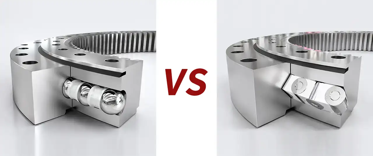
- Unsafe Zone: If the point falls above or to the right of the line, the bearing is insufficient. You must select a larger diameter or upgrade to a high-capacity three-row roller design.