Table of contents
Full slewing bearing load capacity calculations involve raceway geometry, contact stress analysis, and manufacturer-specific rating curves — not something to eyeball with a napkin formula. But understanding the concepts behind the calculation is exactly what lets you have a productive conversation with a bearing engineer instead of guessing. Here’s the breakdown.
Concept 1: The Three Loads Aren’t Calculated the Same Way
Axial load (Fa) is usually the most straightforward — it’s essentially the total weight bearing straight down through the rotation axis, including the structure, any attachments, and the working load.
Radial load (Fr) comes from horizontal forces acting on the structure — wind load on a crane boom, for example, or lateral forces from an attachment. It’s often smaller than axial load, but not always negligible, especially in outdoor equipment exposed to wind.
Moment load (M) is the one that catches people off guard, because it’s not a simple weight — it’s a torque-like value created when a load acts at a distance from the center of rotation. This is why two machines with identical total weight can have very different moment loads, depending on how far that weight extends from the bearing’s center.
Concept 2: Why Moment Load Is the One to Get Right
Here’s the simplified relationship that matters most:
Moment load ≈ Force × Distance from center of rotation
That “distance” term is why crane and excavator arms are so sensitive to reach. Extending a boom further out doesn’t just add a bit more stress — it directly multiplies the moment load the bearing has to resist, even if the actual weight on the hook hasn’t changed at all.
Simplified example: Imagine a 5,000 N load hanging from a crane arm.
- At 2 meters of reach: Moment ≈ 5,000 N × 2 m = 10,000 N·m
- At 4 meters of reach: Moment ≈ 5,000 N × 4 m = 20,000 N·m
Doubling the reach doubled the moment load — with zero change in the actual weight being lifted. This is exactly why load charts for cranes reduce the maximum allowed weight as reach increases: the bearing (and the rest of the structure) can only handle so much moment load before it exceeds its rated capacity.
Concept 3: Static vs Dynamic Capacity
Manufacturers typically publish two different capacity figures:
- Static load capacity — the maximum load the bearing can handle while stationary or moving very slowly, without permanent deformation of the raceway
- Dynamic load capacity — the maximum load the bearing can handle while rotating, accounting for the repeated stress cycling that occurs with movement
A bearing operating near its static limit while also rotating regularly will typically wear out faster than the static rating alone suggests — which is why duty cycle (how often and how fast the bearing rotates) is part of a complete capacity check, not an afterthought.
Concept 4: Safety Margin Isn’t Optional
Calculated loads should never be matched exactly to a bearing’s rated capacity. A margin is applied on top of your calculated axial, radial, and moment loads to account for:
- Load estimation uncertainty
- Dynamic forces during operation (sudden stops, wind gusts, impact loading)
- Wear over the bearing’s service life
The appropriate margin varies by application and is something to confirm with your engineer or the bearing manufacturer — treating your raw calculated load as the rating you need is a common way selections end up undersized.
Concept 5: Why Manual Calculation Only Gets You So Far
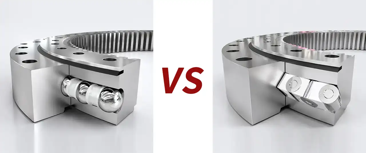
Here’s the honest limit of doing this by hand: actual load capacity depends on raceway hardness, ball or roller size and count, contact angle, and manufacturing tolerances — details that are specific to each manufacturer’s design and typically published in proprietary rating tables or software, not derivable from a generic formula.
In practice, the calculation process most engineers actually follow is:
- Determine your application’s axial, radial, and moment loads (as covered above)
- Apply an appropriate safety margin
- Compare those figures against a manufacturer’s published load rating tables for specific bearing models
- Confirm the selection with the manufacturer’s engineering team, especially for critical or high-load applications
The Takeaway
Understanding how axial, radial, and moment loads are calculated — and why moment load in particular scales with distance from the center of rotation — is what lets you sanity-check a bearing selection and ask the right questions. The final capacity confirmation, though, should always come from matching your calculated loads against a manufacturer’s actual rating data, not a simplified formula alone.